I purchased a few
lens adapters without focus assist chips, to save money. Later I
discovered I could buy the chips cheaply without the lens adapter so
decided to try them out and see how well they work. One added
attraction is that these chips enable manual encoding using the camera,
to provide in EXIF data the lens focal length and maximum f-stop.
I like the idea
of the lens info being provided in the EXIF. Here is the info that
the seller provided along with some additions I made of my own to
explain how to successfully install the chip on the lens adapter.
Note: I have since found a very reliable
seller on eBay that provides the adapter and chip for $12 with free
shipping. I have purchased several and find them to be very
reliable and prefer them to assembling them myself.
emf Smart Adapter
User’s Manual
Main Features
1. Lens maximum aperture
can be set on camera, ranging from F/1.1 to F/45
2. Lens focal length can
be set on camera, ranging from 1mm to 65535mm
3. Focus
micro-adjustment of the lens can be set on camera.
4. Setting data is
stored in the chip on the ring when powered off.
5. The ring enables
camera viewfinder focus confirmation light and confirmation sound.
6. Supports AV (Aperture
Priority) and Manual Mode.
7. Exposure aperture
data can be recorded in EXIF*.
Notes:
EXIF data will contain
the following information as a result of properly setting this chip
·
Lens focal
length in mm
·
Lens maximum
aperture
·
(Lens name
will be shown as “1-65535mm”)
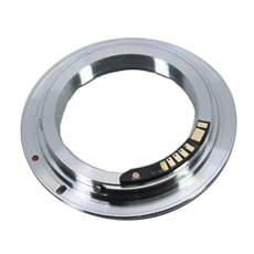
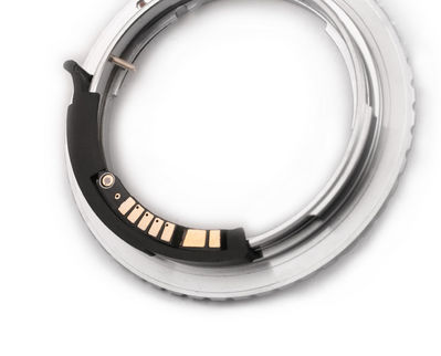
Installation of
Chip onto Lens Adapter (This section only applies to installing
chips to lens adapters that do not already have a chip)
These instructions are
for installing a chip onto a Pentax/M42 to Canon EOS lens adapter.
These instructions would work for any lens adapter that fits a Canon EOS
camera.
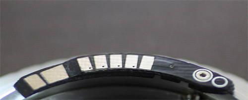
Installation
instructions for this chip were not provided by the seller. After
looking at three pre-assembled lens adapter/chip combinations, it
appears that the chip may be attached to the lens adapter using “gel”
type super-glue, such as this:
1.
Test fit the installation guide so that the
pin fits into the lens adapter locking hole as shown below.
2.
Test fit the chip and become familiar with
the location it will occupy. Note that the installation guide may not
be perfectly sized to allow the chip to fit perfectly. With my chip, I
treated the edge of the guide closest to the lens lock slot as the
indexing point and trimmed the other edge of the installation guide to
allow the chip to fit perfectly between the gap of the guide.
3.
Using some blue painters tape, mark the
position that the chip will occupy leaving the actual surface exposed.
4.
Remove the installation guide temporarily.
With some 1000-grit sandpaper, gently rough up just the portion of the
ring to be covered by the chip. A light scuffing is sufficient.
5.
Rough up the back side of the chip (the side
without the metal contacts).
6.
Clean both the lens adapter ring and the
backside of the chip with a paper towel dampened in alcohol. Make sure
the towel is almost dry to the touch so that no fluid seeps into the
chip.
7.
Place the installation guide onto the lens
adapter as before and use some tape to mask off the area that is NOT
occupied by the chip. This will prevent the glue from making contact
with the portion of the ring that will not be covered by the chip.
8.
Tape the installation guide to the lens
adapter ring in the proper position to align the chip in the correct
position. Test fit the chip again to make sure that it fits in the gap
of the installation guide and lies flat on the lens adapter. Remove the
chip being careful not to get anything on it, and set is aside for a
moment.
9.
Place a small bead of glue on the lens
adapter where the chip will be located. Be careful not to use too much
glue. A small line roughly one quarter the width of the surface, drawn
down the middle of the location, and starting and ending a little ways
in from the end points, will be enough glue to hold the chip in place,
preventing excess glue escaping from beneath the chip when put into
place.
10.
Carefully place the chip in place and align
with the installation guide. Hold the chip firmly in place for a
minute, being careful not to get any glue on the metal contacts.
11.
Set the assembly aside to dry for 10
minutes.
12.
Carefully untape and remove the installation
guide. Some glue may seep beneath the installation guide so take your
time and slowly coax it loose.
13.
Inspect the assembly to be sure no excess
glue has contaminated the contacts, or fouled the lens adapter threads
or bayonet fittings. If any glue has made it onto the contacts,
carefully clean it off with knife being careful not to scratch or dent
the contacts. Better not to get glue on the contacts…
Shooting with Smart Adapter
(This
portion of the guide was provided by the seller. It has been edited to
improve the translation to English.)
*Shooting and
Recording exposure aperture data
Notice: Please set up
the adapter before use.
[See the
How to Setup the Adapter
section]
You can:
1. Set the maximum
aperture on lens
2. Set the desired
aperture on camera
3. Focus and meter the
object, when focus is achieved.
4. Set the lens maximum
aperture to the same aperture as the camera setting
5. Press shutter button
and take the picture.
And you can also:
1. Set the maximum
aperture on lens
2. Set the aperture
value on camera to maximum lens aperture
3. Focus and meter the
object, when focus is achieved.
4. Set the lens aperture
AND the camera aperture setting to the desired aperture.
5. Press shutter button
and take the picture
Shooting and not
recording exposure aperture setting
1. Set the aperture
value on camera to the lens maximum aperture
2. Set the camera to AV
mode
3. Set the desired
aperture on lens
4. Focus and meter the
object and take the picture.
Exposure aperture data
recorded in EXIF is the lens maximum aperture.
How to Set Up the
emf chip Smart Adapter
0. If the chip seems unresponsive, try using a
rubber eraser on the contacts (away from your camera and lens) to clean
the contacts - I have found this works very well)
1. Attach the adapter to
the lens. (Note: emf chip has already been attached to the lens
adapter)
Attach the lens to the camera when camera is
powered off.
Power on the camera and set the camera to
Manual mode.
Set the camera in single shot drive mode. Set
the shutter speed to 1/60 second and aperture increment step to 1/3 EV.
Notice: Do not set the camera in
continuous shooting mode to avoid incorrect operation.
2. Turn the aperture
setting dial and set the aperture value to F/64 and press shutter button
once.
3. Turn the aperture
dial and set the aperture value to F/57 and press shutter button once.
4. Turn the aperture
dial and set the aperture value to F/64 and press shutter button once.
The operation combination of F/64-shutter
button+F57-shutter button +F/64-shutter button will activate the setting
mode of the ring.
5. Turn the aperture
dial. If the maximum aperture value can be set to F/1.0, your ring is
now in set-up mode. You can begin to set the focal length, maximum
aperture value and focus micro adjustment of your lens.
How to enter values
in setting mode
When setting up the
ring, you will need to enter some values. In setting mode, the ring
interprets specified aperture values to numbers. The conversion rule is
stated in the chart below:
|
F/2.0 |
F/2.2 |
F/2.5 |
F/2.8 |
F/3.2 |
F/3.5 |
F/4.0 |
F/4.5 |
F/5.0 |
F/5.6 |
|
0 |
1 |
2 |
3 |
4 |
5 |
6 |
7 |
8 |
9 |
The ring has THREE
setting modes:
Mode 0-
Enter lens Maximum Aperture.
Mode 1-
Enter lens Focal Length.
Mode 2-
Enter lens Focus Micro Adjustment.
Turn the aperture dial
to a specific aperture value and press shutter button to enter a desired
setting mode. For example, if you want to enter the lens maximum
aperture, turn the aperture dial to F/2.0 (which means Mode 0 to the
ring) and press shutter button. You are setting the ring in Maximum
Aperture enter mode.
Enter the Maximum
Aperture
1. Turn the dial and set
the aperture to F/2.0 and press shutter button to enter this mode.
2. Turn the dial and set
the aperture to the actual maximum aperture of your lens and press
shutter button. The maximum aperture will be registered in the ring.
The ring accepts aperture value ranging from F/1.1 to F/45.
Notice:
Do not set the maximum to F/1.0. This
value is reserved for engineering purposes and will not be accepted by
the ring.
Do not set the maximum aperture smaller
than F/5.6. The focus detecting system of your digital camera might fail
to function properly when a lens slower than F/5.6 is attached.
Follow instructions in the
“Store the Parameters to emf Chip” section to save the setting.
Enter the Focal
Length
1. Turn the dial and set
the aperture to F/2.2 and press shutter button to enter this mode.
2. Focal length can be
set from 1mm to 65535mm. The ring needs five digits to store the focal
length data. If the focal length of your lens is smaller than five
digits, you need to insert zeros in front of actual numbers. Each time
you choose a number, press shutter button to enter.
Follow instructions in the
“Store the Parameters to emf Chip” section to save the setting.
For
example, if the focal length of your lens is50mm, you shall enter 00050,
that will be a combination of operations: F/2.0-shutter + F/2.0-shutter
+ F/2.0-shutter + F/3.5-shutter + F/2.0-shutter.
Enter Focus Micro
Adjustment
1. Turn the dial and set
the aperture to F/2.5 and press shutter button to enter this mode.
emf chip accepts focus
micro adjustment value, ranging from 0 to 31. The value is defined by
two numbers. If the micro adjustment value of your lens is smaller than
two numbers, you shall insert a zero in front of the actual number.
Choose the desired number and press shutter button to enter the value
one by one.
Follow instructions in the
“Store the Parameters to emf Chip” section to save the setting.
For
example, if the micro adjustment value is 25, you shall enter F/2.5 -
shutter button + F/3.5 – shutter button
Note: Please enter the
micro adjustment value according to your own tests. The value shall not
be entered based on calculation alone.
Store the Parameters
to emf Chip
When you finish entering
all the parameters of your lens, store them in the chip for normal
shooting.
Here is how:
Change the aperture
value to F/57, press shutter button once.
Change the aperture
value to F/64, press shutter button once.
Change the aperture
value to F/57 again, press shutter once.
If all the values you’ve
entered are correct, the above three steps will store all the parameters
you’ve just entered to the chip on emf chip.
If you missed a step in
the entering process or the value you’ve entered does not fit the value
range requirement stated above, the ring will automatically exit set-up
mode and no parameters will be stored in the ring.
All the data stored in
emf chip will not be lost when camera is powered off.
The default parameter
setting of the emf chip is 50mm F/1.4. Please change the parameters
according to your lens’ specifications.
Caution:
1. Do not touch the
golden contact points of the circuit board of emf chip when attaching
and detaching the ring to your lens and camera.
2. Do not use
F/64-shutter + F/57- shutter + F/64 – shutter combination in normal
shootings. This combination will set emf chip to setting up mode. If
you unintentionally enter this mode, choose an aperture value between
F/6.3 and F/51 and press shutter button once to exit.
Notes:
If
the chip does not operate check to make sure the contacts are clean. If
glue gets on one of the metal contacts during installation, carefully
remove it without damaging the metal contact.
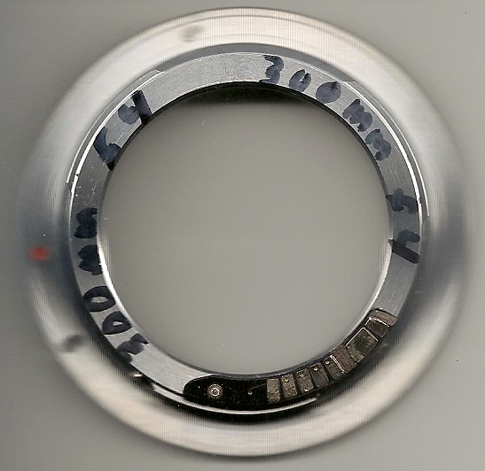
Each
parameter (lens maximum aperture, lens focal length) may be set and
stored separately.
Purchase multiple chips and label the lens adapter ring with the
current setting using a Sharpie or other permanent marker.